 EN
EN

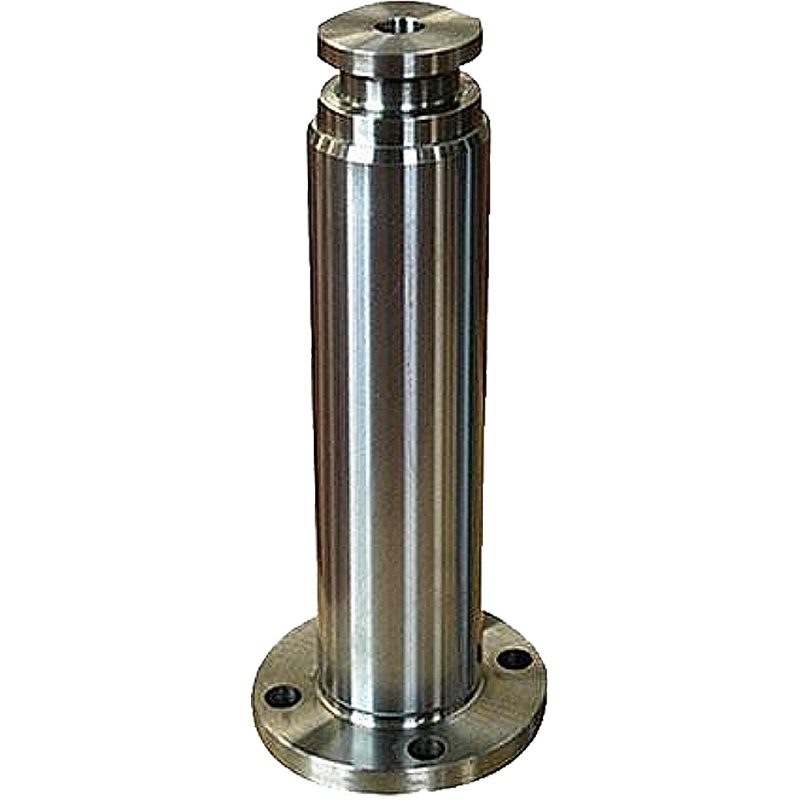
Every hydraulic car lift relies on intact piston rods to maintain stable lifting force, leak-free operation and long seal service life. Tiny invisible surface cracks, abrasive scoring or subsurface voids will trigger seal damage, hydraulic fluid leakage and sudden equipment breakdown if left undetected.
This complete inspection tutorial covers three core testing workflows including visual surface inspection, non-destructive flaw detection and precision geometry calibration. All standards align with ASME, ISO and ASTM industrial specifications, tailored for workshop maintenance teams, hydraulic equipment manufacturers and third-party NDT technicians.
Visual Inspection of Piston Rod Surface: Detect Micro-Cracks, Pitting & Corrosion
Unaided eyes cannot capture microscopic surface defects that shorten piston rod fatigue life. Magnified visual inspection acts as the first mandatory step for all routine lift maintenance.
Stress corrosion cracks, thermal fatigue branching cracks and corrosion pits all start as invisible micro-flaws on chrome-plated piston rods. Stereo microscope ranging from 10× to 50× magnification makes spreading micro-cracks along seal contact zones fully visible. Pitting corrosion generated by galvanic or crevice reaction forms scalloped-edge craters, and pits deeper than 100 µm reduce rod fatigue life by 40% as recorded in Materials Performance published in 2022. Rust and black oxide corrosion blooms deliver clear signals of ongoing surface degradation even when the rod looks smooth to naked eyes.
Portable digital microscopes equipped with coaxial lighting create clear distinction between harmless shallow scuffs and dangerous penetrating cracks. Replication tape can copy complete surface topography for permanent archive comparison.
Key Inspection Priority Area
All inspectors should focus attention on wiper grooves and seal mating surfaces. These zones trap moisture, metal debris and workshop contaminants where the vast majority of surface defects take shape.
Rejection Standard Compliant With ASME B46.1
Any crack extending over 0.5 mm when viewed under 30× magnification requires immediate piston rod replacement. Technicians need to capture photomicrographs of all defects and cross-check against manufacturer acceptance criteria to complete formal maintenance records.
Assess Abrasive Wear Patterns Specific To Hydraulic Car Lift Working Environments
Workshop lift piston rods slide repeatedly against guide bearings and oil seals while exposed to silica dust, metal wear particles and degraded hydraulic oil, which leaves unique abrasive wear marks on rod surfaces. Longitudinal scoring appears as parallel straight scratches formed by embedded hard debris. Circumferential grooves come from uneven bearing loading during frequent lifting cycles. Frosted matte stroke zone refers to uniform fine abrasion covering full sliding travel.
A field survey completed in 2023 covering one hundred and fifty auto workshop lifts proves most piston rods with measurable diameter loss carry typical washboard alternating polished and dull bands, shaped by equipment vibration and unbalanced bearing pressure.
Critical Failure Threshold
Once the outer chrome plating wears through and exposes base steel material, the anti-corrosion protective barrier disappears completely. This change rapidly accelerates seal cutting and hydraulic fluid bypass leakage. A profilometer serves as reliable equipment to measure wear depth, and any abrasion over 0.05 mm demands re-chroming treatment or full rod replacement. Maintenance staff can match collected wear data with total lift cycle counts to build accurate predictive maintenance schedules.
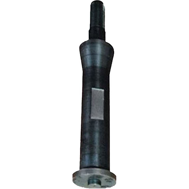
Non-Destructive Testing (NDT): Locate Subsurface Hidden Flaws Without Disassembly
Visual inspection only covers defects existing on rod surfaces. Subsurface micro-cracks, metal inclusions and internal void clusters stay invisible even under high magnification, yet these hidden flaws lead to catastrophic brittle fracture under cyclic lifting loads. Magnetic particle inspection and ultrasonic testing represent two mainstream NDT methods designed for ferrous piston rods.
Magnetic Particle Inspection For Ferrous Piston Rod Subsurface Defects
Magnetic particle inspection creates controlled magnetic field on carbon or alloy steel piston rods, applying fine iron particles to mark subsurface discontinuities located up to 3 mm below the surface.
Compliance Standard Based On ASME Section V Released In 2023
To realize stable detection of linear flaws longer than 1.5 mm, the magnetic flux density must reach minimum 2 kA/m.
Dual Magnetization Operation Standard
Technicians first coat ground rod surface with contrasting background paint, then magnetize the rod in two orthogonal directions to capture both transverse and longitudinal fatigue cracks. Dual-direction magnetization pushes defect detection rate above 90% under standardized testing environments.
For hydraulic car lifts undertaking thousands of daily load cycles, magnetic particle inspection captures subsurface fatigue cracks long before they expand and break through rod surfaces.
Ultrasonic Testing Sensitivity Calibration For Internal Voids & Slag Inclusions
Ultrasonic testers emit high-frequency sound waves into piston rods and analyze reflected echo signals to map internal defect size and depth, with calibration standards fully matching ASTM E213 issued in 2022. Small 5 MHz probes resolve tiny gas pores and slag inclusions as small as 0.8 mm for thin-diameter piston rods. Testing sensitivity gets calibrated to target 2 mm equivalent flaw size since smaller natural metallurgical inclusions barely impact fatigue service life of tempered alloy steel. A-scan waveform filters out irrelevant noise, and inspectors ignore signal peaks with peak-to-background ratio lower than 6 dB to avoid false defect reports. Low-frequency 2.25 MHz probes achieve penetration depth up to 500 mm for thick-section rods equipped on large hydraulic presses and deliver complete cross-section volume coverage.
Real-time coupling monitoring maintains consistent sound transmission across the entire rod surface, and sudden signal attenuation works as an early warning sign pointing to potential internal voids or crack clusters.
Precision Geometry & Alignment Measurement To Eliminate Side Load Damage
Minor bending, twist or bore roundness deviation creates uneven side loads during lifting operations. Extra side loads raise friction coefficient, accelerate bearing wear and cut seal lifespan by over 30%. Three layers of precision measurement work together to guarantee perfect alignment before piston rod reinstallation.
Measure Rod Bend, Twist & Straightness With V-Blocks, Dial Indicators & CMM
Basic total indicator reading straightness test starts with supporting piston rod bearing journals on precision V-blocks. Staff rotate the rod manually while dial indicator touches rod midpoint to read total indicator reading data for quantifying total bend value. The industry tolerance standard sets 0.01 mm straightness deviation per 100 mm rod length following ISO 1101 published in 2017.
Twist angular displacement calculation relies on measuring axial runout at two separated rod positions then calculating angular twist offset between two measurement points.
Coordinate measuring machine delivers full three-dimensional digitization and captures tiny deformations as low as 4 µm plus 4L/1000 µm based on official 2023 CMM specifications. This multi-layer testing workflow reduces measurement uncertainty by 40% compared with single-instrument inspection and fully maps subtle deformation risks hidden on piston rods. Teams combine tactile dial indicator data with optical CMM probing to generate complete no-load alignment reports for reference.
Optical Profilometry For Piston Rod Bore Roundness Deviation Test
Optical profilometry adopts structured light scanning technology to complete non-contact three-dimensional surface reconstruction and measures roundness with sub-micron repeatability reaching 0.1 µm, fully meeting strict requirements of high-pressure hydraulic systems.
ISO 1101:2017 Roundness Evaluation Rule defines roundness deviation as radial gap between two concentric circles wrapping the actual rod profile. Standard acceptable tolerance for lifting equipment piston rods sets maximum 0.005 mm roundness error. Built-in software automatically calculates minimum circumscribed circle, maximum inscribed circle and least-squares circle, outputting full roundness analysis data within seconds. Inspectors compare measured roundness data against ISO tolerances to decide whether re-machining treatment or continuous service applies to tested piston rods.
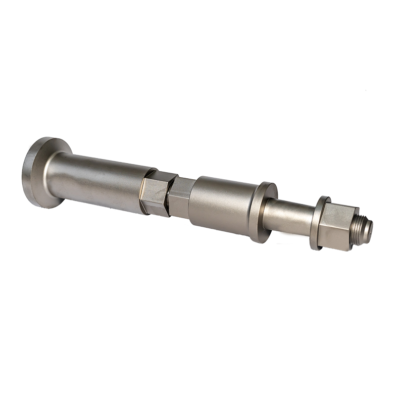
Functional Impact Assessment: How Piston Rod Defects Damage Hydraulic Lift Performance
All detected surface and subsurface flaws trigger cascading operational failures on hydraulic car lifts. Surface micro-cracks, pitting and abrasive scoring heavily cut seal lifespan and cause internal hydraulic fluid bypass together with system pressure loss. Rod bend and twist generate persistent side loads which lead to higher friction, uneven bearing abrasion and continuous equipment vibration, reducing seal life by 30% or more. Subsurface inclusions and voids identified via magnetic particle inspection or ultrasonic testing act as stress concentration points under cyclic lifting loads, and non-metallic impurities can shorten piston rod fatigue life by up to 80% in high-cycle workshop environments.
Defects left uninspected expand rapidly during daily operation and eventually cause brittle rod fracture alongside catastrophic cylinder breakdown, bringing costly unplanned workshop downtime. Systematic defect impact evaluation converts raw inspection data into clear maintenance actions covering surface repair, re-chrome coating or full piston rod replacement.
Frequently Asked Questions
Why is visual magnified inspection the first step for piston rod maintenance
Magnified visual inspection locates surface micro-cracks, corrosion pits and abrasive scoring invisible to human eyes. These surface defects act as root causes behind most hydraulic seal failure and premature piston rod aging on car lifting devices.
What advantages do NDT magnetic particle inspection and ultrasonic testing bring to piston rod testing
Magnetic particle inspection and ultrasonic testing detect hidden subsurface voids, fatigue cracks and metal inclusions without disassembling hydraulic cylinder assemblies. Early identification of internal flaws avoids sudden lift breakdown and expensive emergency repair expenses.
How does abrasive wear damage hydraulic car lift piston rods
Embedded workshop dust and metal particles create longitudinal scoring and circumferential grooves which wear away protective chrome plating layers. Once base steel material gets exposed, corrosion spreads at fast speed, repeatedly cutting oil seal surfaces and triggering hydraulic fluid leakage.
What measuring tools confirm piston rod geometry and alignment
Precision V-blocks, dial indicators and coordinate measuring machines work in tandem to test rod straightness, bend, twist and bore roundness, eliminating alignment errors that create destructive side loads during lifting cycles.
What operational losses do piston rod defects cause
Surface and subsurface flaws accelerate seal and bearing wear, produce misalignment vibration, and form stress concentration zones on rod bodies. Unaddressed defects drastically shorten component service life and may lead to complete hydraulic cylinder system failure.
Final Takeaway
A standardized three-stage piston rod inspection workflow covering magnified visual surface screening, subsurface non-destructive flaw detection and precision geometry calibration becomes essential support for auto lift workshop predictive maintenance. Following industrial standards issued by ASME, ISO and ASTM minimizes unexpected equipment downtime, extends piston rod and seal service life, and cuts long-term hydraulic system repair costs. Maintenance teams match inspection findings with clear reject tolerances to build repeatable, data-driven maintenance procedures applicable to all lifting equipment on site.
Table of Contents
- Visual Inspection of Piston Rod Surface: Detect Micro-Cracks, Pitting & Corrosion
- How To Identify Hidden Surface Discontinuities Under Stereo Microscope
- Non-Destructive Testing (NDT): Locate Subsurface Hidden Flaws Without Disassembly
- Precision Geometry & Alignment Measurement To Eliminate Side Load Damage
- Functional Impact Assessment: How Piston Rod Defects Damage Hydraulic Lift Performance
-
Frequently Asked Questions
- Why is visual magnified inspection the first step for piston rod maintenance
- What advantages do NDT magnetic particle inspection and ultrasonic testing bring to piston rod testing
- How does abrasive wear damage hydraulic car lift piston rods
- What measuring tools confirm piston rod geometry and alignment
- What operational losses do piston rod defects cause
- Final Takeaway